Wednesday, February 6, 2013

SPAN On Cisco Catalyst Switches - Monitor & Capture Network Traffic/Packets

Thanks to www.firewall.cx for providing the context of this article. I've actually had to setup a SPAN port when setting up the Enterasys Dragon IPS/IDS. This setup allowed all internet based traffic to be copied onto the analyzer and sent us Admins any notifications on suspicious traffic. Very useful!


SPAN Terminology

  • Ingress Traffic: Traffic that enters the switch
  • Egress Traffic: Traffic that leaves the switch
  • Source (SPAN) port: A port that is monitored
  • Source (SPAN) VLAN: A VLAN whose traffic is monitored
  • Destination (SPAN) port: A port that monitors source ports. This is usually the point to which a network analyzer is connected.
  • Remote SPAN (RSPAN): When Source ports are not located on the same switch as the Destination port. RSPAN is an advanced feature that requires a special VLAN to carry the monitored traffic and is not supported by all switches.


Source SPAN ports are monitored for received (RX), transmitted (TX) or bidirectional (both) traffic.  Traffic entering or exiting the Source SPAN ports is mirrored to the Destination SPAN port. Typically, you would connect a PC with a network analyzer (Wire Shark or Colasoft) on the Destination SPAN port, and configure it to capture and analyze the traffic.
The amount of information you can obtain from a SPAN session really depends on how well the captured data can be interpreted and understood. Tools such as Capsa Enterprise will not only show the captured packets but automatically diagnose problems such as TCP retransmissions, DNS failures, slow TCP responses, ICMP redirect messages and much more. These capabilities help any engineer to quickly locate network problems which otherwise could not be easily found.

Limitations of Source Ports

A source port has the following characteristics:
  • It can be any port type such as Ether Channel, Fast Ethernet, Gigabit Ethernet and so forth.
  • It can be monitored in multiple SPAN sessions.
  • It cannot be a destination port (that’s where the packet analyzer is connected)
  • Each source port can be configured with a direction (ingress, egress, or both) to monitor. For Ether Channel sources, the monitored direction applies to all physical ports in the group.
  • Source ports can be in the same or different VLANs.
  • For VLAN SPAN sources, all active ports in the source VLAN are included as source ports.


Limitations of Destination Ports

Each SPAN session must have a destination port that receives a copy of the traffic from the source ports and VLANs.
A destination port has these characteristics:
  • A destination port must reside on the same switch as the source port (for a local SPAN session).
  • A destination port can be any Ethernet physical port.
  • A destination port can participate in only one SPAN session at a time.
  • A destination port in one SPAN session cannot be a destination port for a second SPAN session.
  • A destination port cannot be a source port.
  • A destination port cannot be an Ether Channel group.

Limitations of SPAN on Cisco Catalyst Models

Following are the limitations of SPAN on various Cisco Catalyst switches:
  • Cisco Catalyst 2950 switches are only able to have one SPAN session active at a time and can monitor source ports. These switches cannot monitor VLAN source.
  • Cisco Catalyst switches can forward traffic on a destination SPAN port in Cisco IOS 12.1(13)EA1 and later
  • Cisco Catalyst 3550, 3560 and 3750 switches can support up to two SPAN sessions at a time and can monitor source ports as well as VLANs
  • The Catalyst 2970, 3560, and 3750 Switches do not require the configuration of a reflector port when you configure an RSPAN session.
  • The Catalyst 3750 Switches support session configuration with the use of source and destination ports that reside on any of the switch stack members.
  • Only one destination port is allowed per SPAN session and the same port cannot be a destination port for multiple SPAN sessions. Therefore, you cannot have two SPAN sessions that use the same destination port.

Configuring SPAN On Cisco Catalyst Switches

Our test-bed was a Cisco Catalyst 3550 Layer 3 switch, however, the commands used are fully supported on all Cisco Catalyst 2940, 2950, 2955, 2960, 2970, 3550, 3560, 3560−E, 3750, 3750−E and 4507R Series Switches.
The diagram below represents a typical network setup where there is a need to monitor traffic entering (Ingress) and exiting (Egress) the port to which the router connects (FE0/1). This strategically selected port essentially monitors all traffic entering and exiting our network.


Since router R1 connects to the 3550 Catalyst switch on port FE0/1, this port is configured as the Source SPAN port. Traffic copied from FE0/1 is to be mirrored out FE0/24 where our monitoring workstation is waiting to capture the traffic.

Because serious network procedures require serious tools, we opted to work with Colasoft’s Capsa Enterprise edition, our favourite network analyser. With Caspa Enterprise, we were able to capture all packets at full network speed and easily identify TCP sessions and data flows that we were interested in. If you haven’t tried Capsa Enterprise yet, we would highly recommend you do by visiting Colasoft’s website and downloading a copy.
Once we have our network analyser setup and running, the first step is to configure FastEthernet 0/1 as a source SPAN port:
 
Catalyst-3550(config)# monitor session 1 source interface fastethernet 0/1

Next, configure FastEthernet 0/24 as the destination SPAN port:
 
Catalyst-3550(config)# monitor session 1 destination interface fastethernet 0/24

After entering both commands, we noticed our destination’s SPAN port LED (FE0/24) began flashing in synchronisation with that of FE0/1’s LED – an expected behaviour considering all FE0/1 packets were being copied to FE0/24.
Confirming the monitoring session and operation requires one simple command, show monitor session 1:
Catalyst-3550#  show monitor session 1Session 1
---------
Type                  : Local Session
Source Ports      :
    Both              : Fa0/1
Destination Ports: Fa0/24
    Encapsulation : Native
          Ingress: Disabled

To display the detailed information from a saved version of the monitor configuration for a specific session, issue the show monitor session 1 detail command:
 
Catalyst-3550# show monitor session 1 detail
Session 1
---------
Type              : Local Session
Source Ports      :
    RX Only         : None
    TX Only         : None
    Both              : Fa0/1
Source VLANs    :
    RX Only       : None
    TX Only       : None
    Both            : None
Source RSPAN VLAN : None
Destination Ports      : Fa0/24
    Encapsulation       : Native
          Ingress:         Disabled
Reflector Port           : None
Filter VLANs              : None
Dest RSPAN VLAN    : None
 
Notice how the Source Ports section shows Fa0/1 for the row named Both. This means that we are monitoring both RX & TX packets for Fa0/1, while the Destination Port is set to Fa0/24.


Friday, January 18, 2013

Configure Static NAT for Inbound Connections.

How to configure Network Address Translation (NAT) so that computers on the Internet could access a internal Web and mail server through a Cisco router. This requires configuring a static NAT translation between the dedicated public IP address and the internal private IP address.

NAT transforms private IP addresses to public IP address so users can access the public Internet. Most of us use a form of NAT calledPort Address Translation (PAT), which Cisco refers to as NAT overload. ( How to Set up NAT using the Cisco IOS and How to Set up PAT (Port Address Translation) in the Cisco IOS.”)

Figure A a diagram to help visualize the network.
How to Configure Static NAT for Inbound Connections

Goal: To configure a static IP translation through the router from the outside (i.e., Internet) network to the inside (i.e., private) network.

Here’s the information we need for the example:
  • Router inside interface E0/0: IP 10.1.1.1
  • Router outside interface S0/0: IP 63.63.63.1
  • Web/mail server private IP: 10.1.1.2
  • Web/mail server public IP: 63.63.63.2
There are two important steps to get this traffic inside your network and to your Web/mail server:
  1. NAT configuration
  2. Firewall configuration
In this post, I’ll provide the basic static NAT configuration.

Note: However, make sure that whatever you’re using for your firewall it also allows this traffic in.
Whether you’re using basic Access Control Lists (ACLs) or the Cisco IOS firewall feature set, make sure you understand how to configure your firewall for the right IP addresses (public or private). In other words, what happens first — NAT translation or firewall filtering? For example, when using ACLs, a check of the input ACL occurs before NAT translation. So, you need to write ACLs with the public IP addresses in mind.

Basic configuration:
interface Serial0/0
ip address 63.63.63.1 255.255.255.0
ip nat outside
interface Ethernet0/0
ip address 10.1.1.1 255.255.255.0
ip nat inside
We need the NAT translations to translate the outside IP address of the Web/mail server from 63.63.63.2 to 10.1.1.2 (and from 10.1.1.2 to 63.63.63.2). Here’s the command to link between the outside and inside NAT configurations:
Router (config)# ip nat inside source static tcp 10.1.1.2 25 63.63.63.2 25
Router (config)# ip nat inside source static tcp 10.1.1.2 443 63.63.63.2 443
Router (config)# ip nat inside source static tcp 10.1.1.2 80 63.63.63.2 80
Router (config)# ip nat inside source static tcp 10.1.1.2 110 63.63.63.2 110
We used the specific port numbers, 25,443,80,110, because they fit the description of what we want to do. I chose port 25 for SMTP (sending mail), port 443 for HTTPS (secure Web), port 80 for HTTP (Web traffic), and port 110 for POP3 (receiving mail from the mail server when out on the Internet).

The following configuration can also be used if you have been assigned and are using a block of IP addresses. If you don’t, you can use the outside IP address on your router (Serial 0/0 in this case), and configure it like this:
Router (config)# ip nat inside source static tcp 10.1.1.2 25 interface serial 0/0 25
You can also use this command if you have a dynamic DHCP IP address from your ISP on the outside of your router.


In addition to configuring static NAT, you may want to use dynamic NAT at the same time. With this, your inside PCs could access the Internet using dynamic NAT (i.e., NAT overload or PAT). This type of configuration could be a little more complex. I've used this type of setup in the past and if you don't document your configurations correctly, things can get out of hand quickly.

Friday, January 11, 2013

Configuring HSRP on a Cisco IOS Router

Hot Standby Routing Protocol or HSRP, is a Cisco proprietary protocol that allows two or more routers to work together to represent a single IP address for a particular network. HSRP, as well as Virtual Route Redundancy Protocol (VRRP) are considered high-availability network services that allow for almost immediate fail over to a secondary interface when the primary interface becomes unavailable.
HSRP is a fairly simple concept that works by having one router within an HSRP group be selected as the primary or active router. That primary will handle all routing requests while the other routers within the HSRP group simply wait in a standby state. These standby routers remain ready to take on the entire traffic load if the primary router becomes unavailable. In this scenario, HSRP provides high network availability since it routes IP traffic without depending on a single router.

Check out RFC 2281 for full details on HSRP and the inner workings of this widely used protocol.

The hosts that use the HSRP address as a gateway never know the actual physical IP or MAC address of the routers in the group. Only the virtual IP address that was created within the HSRP configuration along with a virtual MAC address is known to other hosts on the network.

Basic HSRP Configuration
Before we discuss more advanced HSRP concepts, lets create a basic HSRP configuration to get an idea of how this all works. For this scenario we will use a topology consisting of just two routers. Keep in mind that one or both of these routers could be multilayer switches such as a 6509 or 3750 as well. I had two Cisco ASA5540's setup in this same configuration. Not only did it provide HA and Redundancy but it allowed me to upgrade the IOS and ASDM without having to take anyone offline. This is a big plus especially when data access is critical and outside access is a must. I also didn't like to have to explain to high ranking officials why they couldn't get online.

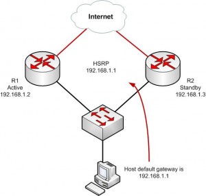
R1 and R2 will both be configured to be in standby group 1. The HSRP address will be given an IP address of 192.168.1.1/24. All hosts on the segment and in the VLAN will use this address as their default gateway.
R1(config)#interface ethernet0
R1(config-if)#ip address 192.168.1.2
R1(config-if)#standby 1 ip 192.168.1.1
R2(config)#interface ethernet0
R2(config-if)#ip address 192.168.1.3
R2(config-if)#standby 1 ip 192.168.1.1

To see the status of HSRP use the command show standby
This is the first command you should run to ensure that HSRP is running and configured properly.

R1#show standby
Ethernet0 – Group 1
Local state is Standby, priority 100
Hellotime 3 sec, holdtime 10 sec
Next hello sent in 0.776
Virtual IP address is 192.168.1.1 configured
Active router is 192.168.1.3, priority 100 expires in 9.568
Standby router is local
1 state changes, last state change 00:00:22

R2#show standby
Ethernet0 – Group 1
Local state is Active, priority 100
Hellotime 3 sec, holdtime 10 sec
Next hello sent in 2.592
Virtual IP address is 192.168.1.1 configured
Active router is local
Standby router is 192.168.1.2 expires in 8.020
Virtual mac address is 0000.0c07.ac05
2 state changes, last state change 00:02:08

We can see that R2 has been selected as the Active router (“Local state is Active”), the virtual router’s IP is 192.168.1.1, and R1 is the stand by router.
How to Configure HSRP on a Cisco Router

Controlling the Active HSRP Router
There are more HSRP values that you’ll need to change from time to time to ensure complete control over your network traffic. For example, what if we wanted R1 to be the Active router instead of R2?  To force a particular router to be the active router in an HSRP group you will need to use the priority command.
The default priority is 100.  The higher priority will determine which router is active.  If both routers are set to the same priority, the first router to come up will be the active router.
Using our example above, this is how the commands would look.

R1(config)#interface ethernet0
R1(config-if)#ip address 192.168.1.2
R1(config-if)#standby 1 ip 192.168.1.1
R1(config-if)#standby 1 priority 200<– Add this to force R1 to be active
R2(config)#interface ethernet0
R2(config-if)#ip address 192.168.1.3
R2(config-if)#standby 1 ip 192.168.1.1

Keeping the Active Router Active
In our scenario above, if R1 fails, R2 will become active.  This is perfect!  But, if R1 comes back up and returns to service, R2 will continue to stay active.  This may not be a preferred behavior.  There are times when you may always want R1 to be in an active state in the HSRP group.  Cisco provides a way for use to control this by using the Preempt command.  Preempt forces a router to be active after recovering from a failure.
Here again is our two router topology, with the preempt command added.

R1(config)#interface ethernet0
R1(config-if)#ip address 192.168.1.2
R1(config-if)#standby 1 ip 192.168.1.1
R1(config-if)#standby 1 priority 200
R1(config-if)#standby 1 preempt<– Add this to force R1 to return to active state after failure
R2(config)#interface ethernet0
R2(config-if)#ip address 192.168.1.3
R2(config-if)#standby 1 ip 192.168.1.1

Advanced HSRP Configuration – Load Balancing
So now you can see how great HSRP is and how it allows us to have high availability between multiple routers for a single network.  But our standby routers aren’t doing anything and are just sitting there!   Depending on the model router you are using, this can be a lot money just sitting idle.
To solve this problem, we can configure HSRP to be load balanced between routers.  This doesn’t help us with a single HSRP group, but for multiple HSRP groups we can spread the load and have each HSRP group be active on different routers.
By configuring multiple HSRP groups on a single interface, HSRP load balancing can be achieved.
Here is how we accomplish this.
R1(config)#interface ethernet0
R1(config-if)#ip address 192.168.1.2
R1(config-if)#standby 1 ip 192.168.1.1
R1(config-if)#standby 1 priority 200
R1(config-if)#standby 1 preempt
R1(config-if)#standby 1 name nework-one!
R1(config)#interface ethernet1
R1(config-if)#ip address 10.1.1.2
R1(config-if)#standby 2 ip 10.1.1.1
R1(config-if)#standby 2 name nework-two
R2(config)#interface ethernet0
R2(config-if)#ip address 192.168.1.3
R2(config-if)#standby 1 ip 192.168.1.1
R2(config-if)#standby 1 name nework-one!
R2(config)#interface ethernet1
R2(config-if)#ip address 10.1.1.3
R2(config-if)#standby 2 ip 10.1.1.1
R2(config-if)#standby 2 priority 200
R2(config-if)#standby 2 preempt
R2(config-if)#standby 2 name nework-two
In this example above, ethernet0on Router 1 is active for standby group 1 and Router 2 is standby.  Forethernet1, HSRP group 2, Router 2 is active and Router 1 is standby.   This allows us to have each router working for us and forwarding packets to best utilize our investment in our networking equipment.  We’ve also added the HSRP group name command to help better describe each HSRP group. This can be a life saver when you have several HSRP groups that you need to track.
One last note on HSRP standby groups.  You can have multiple interfaces and networks configured using the same standby group number if the fail over behavior needed is the same.

Configure Static NAT on Cisco IOS

Static NAT on Cisco IOS Routers. Static NAT is a one to one NAT between IP addresses, one Private IP to one Public IP.
 
NAT Inside Interface
Enable one interface on the router with an IP Address, mark it the NAT INSIDE interface. This is the interface that connects to your internal private network
Router(config)# int fastethernet0/1
Router(config-if)# ip address 192.168.1.1 255.255.255.0
Router(config-if)# ip nat inside


Enable NAT Outside Interface
Enable one interface on the router with an IP Address, mark it as the NAT OUTSIDE interface. This is the interface that connects to your outside public network
Router(config)# int serial0/0/0
Router(config-if)# ip address 100.100.100.100 255.255.255.0
Router(config-if)# ip nat outside

Instruct Router to NAT the Source IP Address to that of a NAT'd IP.
Router(config)# ip nat inside source static 192.168.1.2 100.100.100.101
Router(config)# ip nat inside source static 192.168.1.3 100.100.100.102
Router(config)# ip nat inside source static 192.168.1.4 100.100.100.103
Where 192.168.1.x IP's are NAT'd to 100.100.100.x

The syntax is
ip nat inside source static x.x.x.x y.y.y.y
Note: Static NAT's can co-exist with NAT Overloading or Dynamic NATs.

To Check the NAT Status and Statistics
Router# show ip nat statistics

To See the Active Translations
Router# show ip nat translations

Wednesday, January 9, 2013

Configuring (Overloading) NAT in Cisco IOS.

NAT (Network Address Translation), it in simple terms translates an IP address into another. Network Address Translation is of different types like

Static NAT (One to One)
Dynamic NAT (Many to Many)
Overloading (Many to One)

The purpose of NAT is to hide the private IP addresses of a client in order to reserve the public address space. For example a complete network with 254 hosts can have 254 private IP addresses and still be visible to the outside world (internet) as a single IP address. Other benefits include security and economical usage of IP address ranges.
The following will focus on the Overloading form of NAT. This is called Port Address Translation (PAT) or Network Address Port Translation (NAPT). NAT Overloading translates many private IP addresses from a Local Area Network (LAN) onto a single registered Public IP address. Here, the source IP and the source port get translated to the Public IP and a different source port.
Typical network configuration would be on an Internet Router which enables all the hosts in the LAN to connect to the Internet using one single Public IP address.
The following procedure will help you configure NAT Overload or Port Address Translation (PAT) in Cisco IOS:

NAT Inside Interface
Enable an interface on the router with an IP Address and mark it as nat inside interface. This is the interface that connects to your internal private network
Router(config)# int fastethernet0/1
Router(config-if)# ip address 192.168.1.1 255.255.255.0
Router(config-if)# ip nat inside
Enable NAT Outside Interface
Router(config)# int serial0/0/0
Router(config-if)# ip address 100.100.100.100 255.255.255.0
Router(config-if)# ip nat outside
Configure NAT Pool
This will be a pool of legal Public IPs that is bought by the organization. This could anything from one to many IP Address
Router(config)# ip nat pool NATPOOL 100.100.100.10 100.100.100.10 netmask 255.255.255.0
Note: NATPOOL is the name of the pool where addresses will be used from. This can be any name, don't get to complex with the naming.
This creates pool which has just one IP address. The syntax is
ip nat pool <pool name> startip endip {netmask netmask | prefix prefix-length}
Access List to Allow List of IP Addresses to NAT Translate
Router(config)# ip access-list 10 permit 192.168.1.0 0.0.0.255 
For more networks or hosts to overload the NAT pool simply add them to the access list
Router(config)# ip access-list 10 permit 192.168.2.0 0.0.0.255
Router(config)# ip access-list 10 permit 192.168.3.0 0.0.0.255
Instruct Router to NAT the Access list to the NATPool
Router(config)# ip nat inside source list 10 pool NATPOOL overload
If this is an internet configuration then ensure that a default route on the IP to the outside IP address or outside interface
Router(config)# ip route 0.0.0.0. 0.0.0.0 serial0/0/0
or
Router(config)# ip route 0.0.0.0 0.0.0.0 100.100.100.100

The NAT setup is complete.The router has been setup to translate LAN private IPs into the Internet public IPs.
To check the NAT status and statistics
Router# show ip nat statistics
To see the active translations
Router# show ip nat translations